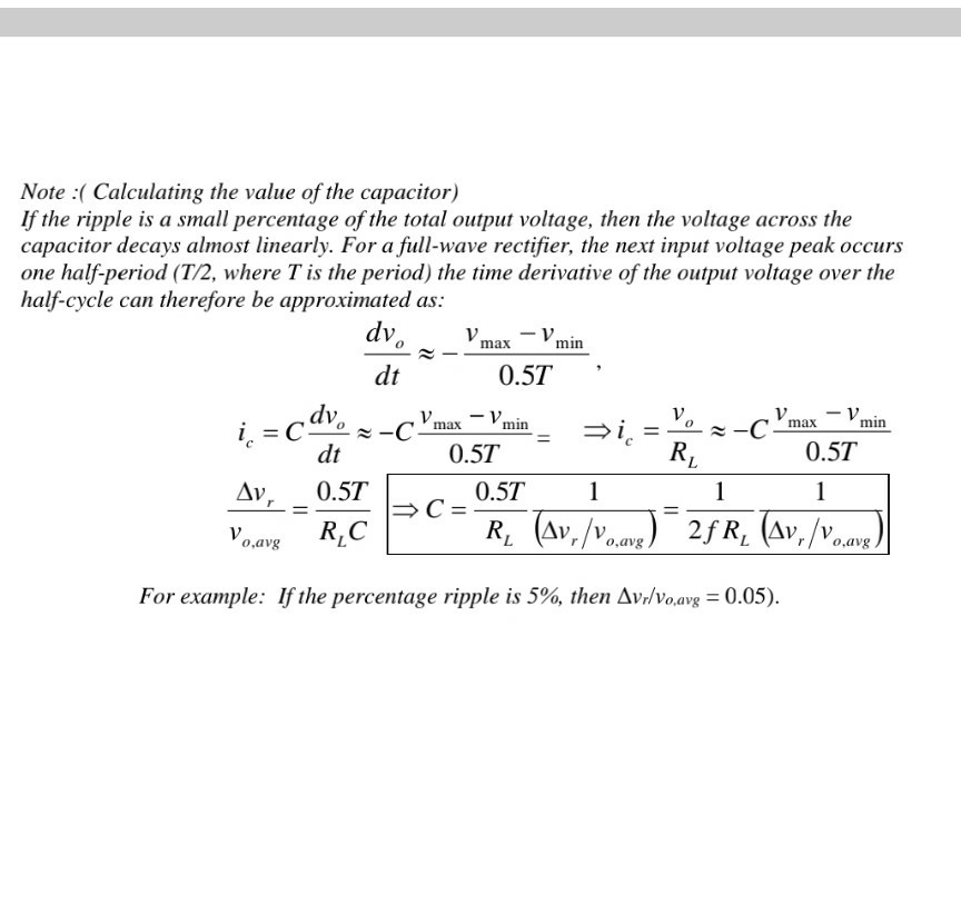
Diode Voltage Regulator Circuit Diagram So voltage regulation with a Zener diode, I guess the summary is it's a challenge, but it's worth it because this is the basis of all modern power supply things. This, in a full-wave rectifier, switching-mode power supplies, you have a lot of different ways of approaching it. But this is one of the key ways that most things have their voltage

When a using Zener diode as a voltage regulator, ideally, it has a constant voltage drop equal to its nominal Zener voltage. This constant voltage drop across the Zener diode produced by reverse breakdown is represented by a DC voltage symbol (figure 1) even though the Zener diode does not produce a voltage. Zener Diode as a Voltage Regulator. There is a series resistor connected to the circuit in order to limit the current into the diode. It is connected to the positive terminal of the d.c. It works in such a way the reverse-biased can also work in breakdown conditions. We do not use ordinary junction diode because the low power rating diode can
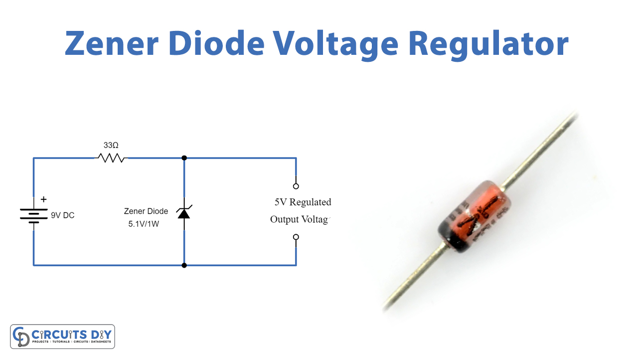
Zener Diode Voltage Regulator Circuit Diagram
A Zener diode voltage regulator is an electrical circuit that maintains a constant DC output voltage using a Zener diode. A perfect regulator would produce a constant voltage regardless of input fluctuations or load current variations. Zener diode is a popular one in types of diode. A Zener diode's ability to maintain almost constant voltage in its breakdown region makes it suitable for regulating voltage even in the simplest voltage regulator applications. A voltage regulator's main role is to deliver a steady output voltage to a load connected in parallel. This is even when the supply voltage has ripples or the load

Using a Zener diode as a voltage regulator has several advantages. It is a simple, cost-effective, and easy-to-implement solution for voltage regulation. By selecting Zener diodes with different breakdown voltages, various output voltage levels can be achieved. This method works well for low-power applications where minor voltage fluctuations

Zener Diode as a Voltage Regulator Circuit Diagram
A Zener diode plays a crucial role in voltage regulation. It is a semiconductor diode that typically blocks current in the reverse direction. However, when the reverse voltage exceeds a specific limit, known as the Zener voltage, the diode allows current to flow while maintaining a constant voltage. This property makes Zener diodes ideal for
The zener voltage regulator consists of a current limiting resistor R S connected in series with the input voltage V S with the zener diode connected in parallel with the load R L in this reverse biased condition. The maximum power rating P Z of the zener diode is 2W. Using the zener regulator circuit above calculate: a). The maximum